I first tried tot block the outlet with some foam and drilled two outlet ports about 10 cm higher.

Unfortunately this was a bit too simple to be KISS. Reverse thrust was great but in forward I had lots of ventilation problems because of the exhaust gasses being sucked to the propellor. I just lost way too much forward thrust.
I tried to overcome this with an extended cavitation plate.

But..... unfortunately this didn't work either.
Searching the internet I found an over 30 year old (!!!) boatingmagazine article by Jan Alkema (a fellow dutchman!) about exactly the same problem. His trick is to redirect/'bend' the exhaust gases upward instead of downward to the propellor with a simple tunnel made of some metal plate.
I made this tunnel with polyester molded over the outboard leg (polyester is terrible to work with, but the good thing is it hardens quickly enough to release the molded part within the hour and take it home).


Molded part laminated with epoxy/glass and some plastic on top to press all the glass together without getting too messy.

No it is not pretty, I don't care as long as it works.

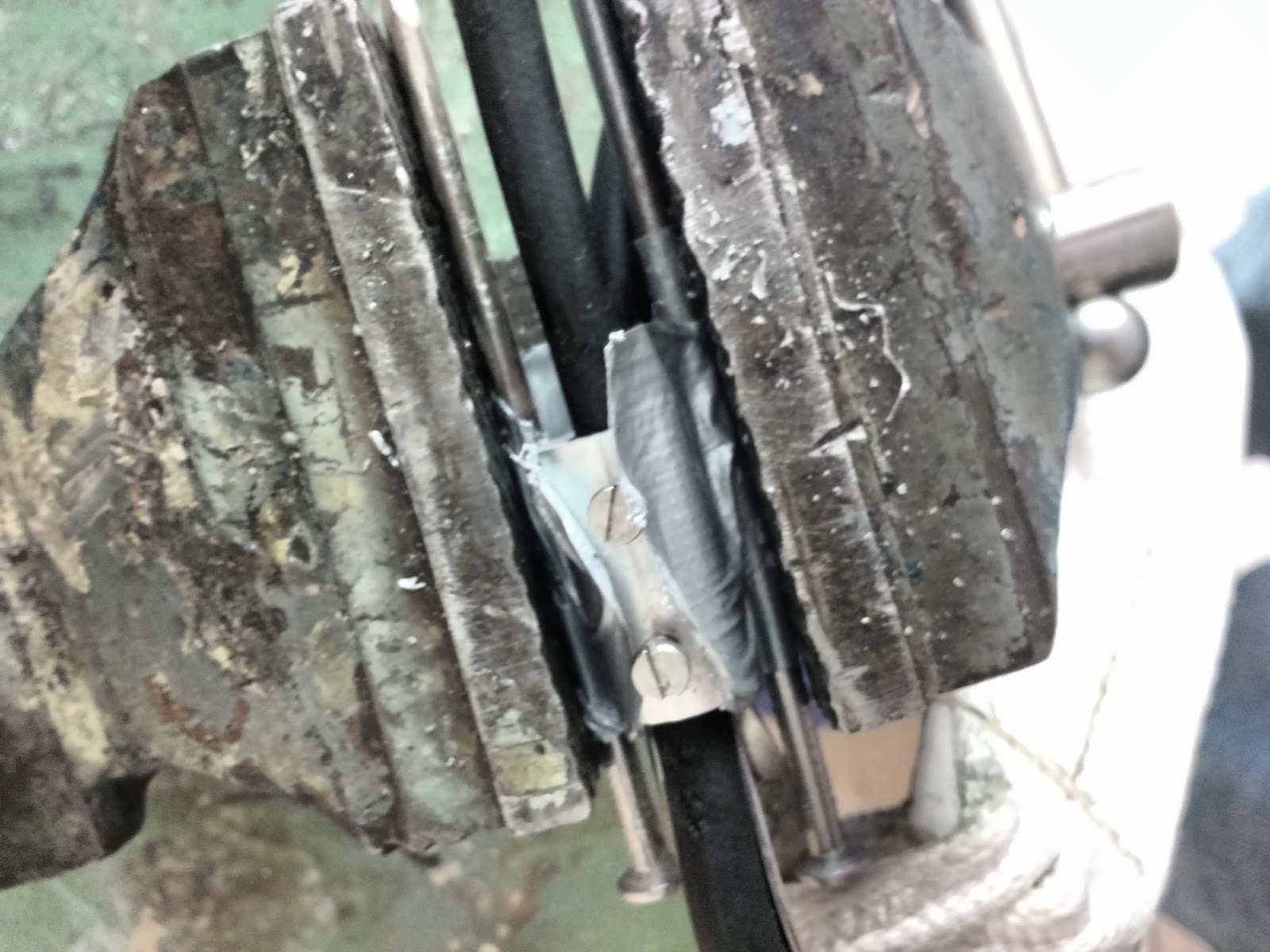
Below: part bolted to the cavitation plate. I covered the holes with some ducktape, and will cover them permanently with some glasstape with polyester wrapped around the leg. Polyester shrinks a lot and will thus result in nice tight fitting band.

Should have done this years ago.......
I thought...... but ........
After a sail a few days ago with lots of wind I had big problems with forward thrust so I removed the modification.
After some googling I noticed on sailing-forums that lots of other people with exactly my outboard (the yamaha 6 hp F6C four stroke) complain about terrible reverse power and are talking about fitting a 'high thrust' propeller (with bigger blades and lower pitch). So I've probably been working in the wrong direction, and should have started with another propeller (as someone also noted in the comments on this post).
I found a shop that sells a 'yamaha double thrust' propeller that according to the shop fits my outboard (although it seems to be designed for Yamaha outboards with a through-prop exhaust which my outboard doesn't have) and will give higher thrust.
I wil try it and else I will dump my outboard which I'm starting to hate, and buy one of the sailpower outboards of mercury or tohatsu that 'according to internet' - in contrast to the standard Yamaha F6C - work for sailboats.